
Cassini MIMI Investigation at Fundamental Technologies
Numerical Computation of Energy-Dependent Geometric Factors of E and F Electron Detectors of CASSINI/MIMI/LEMMS
Technical Report by Xiaodong Hong and Thomas P. Armstrong, May 10, 1997
Chapter 3 Computation of Geometric Factors
After the geometry of the subsystem is modeled with the plane polygons, and the magnetic field is simulated, one would be ready to trace the trajectory of an electron with initial conditions. This tracing process is done in time-reversed mode, i.e., an electron starts from one of the two detector sensors and moves to escape the open aperture. Those that reach the open apertures are the same electrons which can pass through the open aperture and hit the detector sensor and be detected.
When an electron hits any of the polygon planes representing the walls it is terminated; no scattering effect has been taken into account in this study. The program [4] for Ulysses HISCALE electron trajectory tracing is adopted for this project. There are seven hexagonal open apertures and other polygon planes in the geometric modeling of the Cassini/MIMI/LEMMS. Modification has to be done in order to run the program efficiently, especially for the checking impacts on the wall of an open aperture channel.
The tracing procedure of an electron trajectory is described as follows:
1. As mentioned earlier the tracing process is time-reversed; an electron starts from the center of one rectangle with a certain energy. See figure 1.5 and refer to tables 3.1 and 3.2 for coordinates. Notice that only coordinates of a half detector are given because of the symmetric properties of the detector along the z=0 plane. The initial direction of the electron is determined by the azimuthal angle f and the polar angle q. This electron is propelled by the magnetic field produced by the tilted rare-earth magnets and moves out of the chamber.
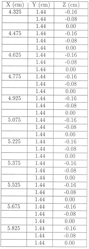
Table 3.1 Coordinates of the starting positions in the E detector
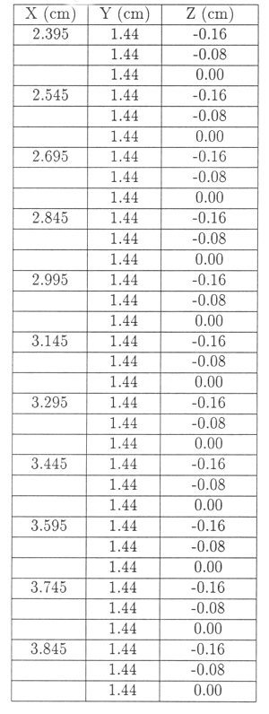
Table 3.2 Coordinates of the starting positions in the F detector
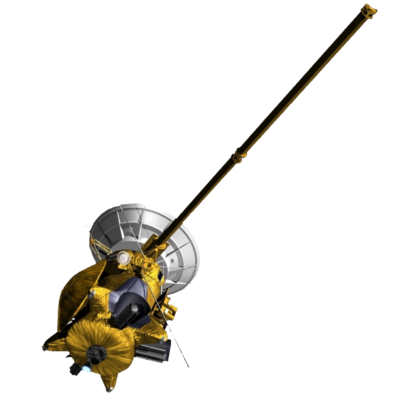
2. The whole chamber consists of four rectangular planes and two trapezoid planes. The proton detector sensor is located in one of the trapezoid planes, and there are seven hexagonal open aperture channels vertically mounted on the other trapezoid plane. Any impact with one of the planes of the chamber except the trapezoid plane which has the open aperture channels would cause the trajectory of the electron to be terminated.
3. If the electron hits the trapezoid plane with open aperture channels, we need to further check the impact location to confirm whether it is on its way out through one of the seven hexagonal open aperture channels. If it is in one of the open aperture channels, later on we only need to trace the trajectory with the hexagonal walls of this particular channel. It would either hit the walls or escape the open aperture. (For the detailed hit checking mechanism please refer to Wu, McKee, Armstrong [1] program code included in Appendix D of this report.)
4. For this energy we need to check all possible directions of an electron. After one has tallied all possible combinations of q and f with certain intervals of Dq and Df (Dq=1º and Df=1º are used in this computation) for a rectangle with area of DAi, one would be able to compute the solid angle for this DAi.
![]()
where qj and fj are the polar and azimuthal angles in which direction an electron escapes an open aperture channel starting from a rectangle i.
5. After we have traced every small rectangular detector sensor with area of DAi then the geometric factor would be the sum [1]:
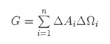
The number of escaped electrons for each rectangle with different energies is given in Appendix B. The plots of the escaped trajectories of some particular starting point with different energies are given in Appendix C. After all the escaped electrons are recorded, one can calculate the geometric factor for each energy in the E or F detector. The results are given and discussed in chapter 4.
Next: Chapter 4 Results and Discussion
Return to Technical Report Table of Contents
Return to Cassini
MIMI table of contents page.
Return to Fundamental
Technologies Home Page.
Updated 8/8/19, Cameron Crane
QUICK FACTS
Mission Duration: The Cassini-Huygens mission launched on October 15 1997, and ended on September 15 2017.
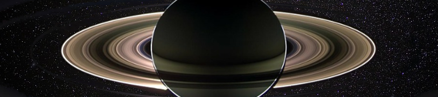
Destination: Cassini's destination was Saturn and its moons. The destination of the Huygens Probe's was Saturn's moon Titan.
Orbit: Cassini orbited Saturn for 13 years before diving between its rings and colliding with the planet on September 15th, 2017.