
Cassini MIMI Investigation at Fundamental Technologies
Numerical Computation of Energy-Dependent Geometric Factors of E and F Electron Detectors of CASSINI/MIMI/LEMMS
Technical Report by Xiaodong Hong and Thomas P. Armstrong, May 10, 1997
Chapter 1 Simulation of the Geometry of the Cassini/MIMI/LEMMS Sensor
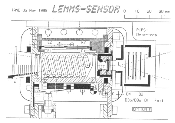
The Cassini/MIMI/LEMMS sensor consists of two rectangular electron detectors and one circular proton detector. The whole system is surrounded by several surfaces with seven hexagonal incoming particle apertures. Two rare-earth magnets are mounted on the left and right sides of the sensor perpendicular to the aperture surface. Each magnet is tilted 14.7º away from the middle plane (z=0) of the sensor. The lower energy electron detector E is located at the smaller side of the trapezoid and closer to the aperture, while the higher energy electron detector F is farther away from the aperture. Both the E and F detectors lie in a plane which is perpendicular to the open aperture. The proton detector is located directly opposite to the open aperture.
A cross section of the Cassini/MIMI/LEMMS is shown in Figure 1.1. In order to trace the trajectory of a particle, whether it collides with the wall of the sensor or the detectors, we need to model the sensor subsystem with plane polygons. Since the Cassini/MIMI/LEMMS has geometry which is similar to Galileo LEMMS, we adopt the software which was applied to the Galileo LEMMS and the coordinates which were used by Wu, McKee, and Armstrong [1] for Galileo LEMMS computation.
Figure 1.1 The cross section of the mechanical drawing of Cassini/MIMI/LEMMS.
Figures 1.2 - 1.4 show the resulting plane polygons of the chamber and open aperture channels with different view angles. There are four rectangular planes and two trapezoid planes for the chamber of the system. The proton detector sensor is located in one of the trapezoid planes, and there are seven hexagonal open aperture channels vertically mounted on the other trapezoid plane. Figure 1.2 also shows the reversed trajectories of escaped electrons starting from (2.545,1.44,0) with energy of 20 keV.
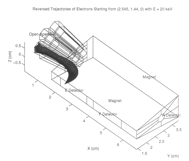 |
Figure 1.2 The polygon modeled geometry of Cassini/MIMI/LEMMS, view angle of q= 45º and f=45º. |
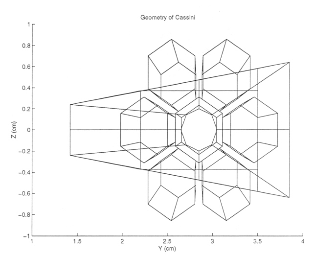 |
Figure 1.3 The polygon modeled geometry of Cassini/MIMI/LEMMS, view angle of q= 0º and f=90º. |
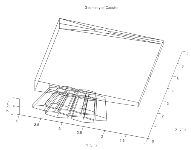 |
Figure 1.4 The polygon modeled geometry of Cassini/MIMI/LEMMS, view angle of q= -75º and f=80º. |
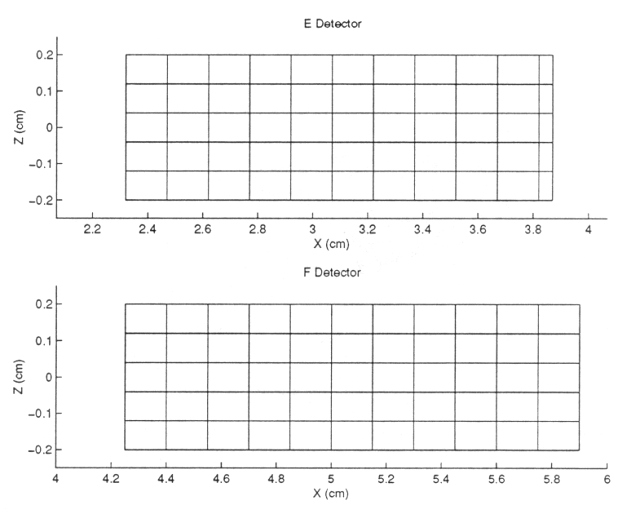
The E and F detectors have dimensions of 0.4 cm x 1.55 cm and 0.4 cm x 1.65 cm respectively. They are divided into five strips along the z direction and eleven strips along the x direction (see Figure 1.5). The trace of the trajectories of electrons is done in reverse, starting from each center point of each divided rectangle (for detailed program please refer to chapter 3).
Figure 1.5 The dimensions of the E and F detectors.
Next: Chapter 2 Calculation of Magnetic Field of the Cassini/MIMI/LEMMS Sensor
Return to Technical Report Table of Contents
Return to Cassini
MIMI table of contents page.
Return to Fundamental
Technologies Home Page.
Updated 8/8/19, Cameron Crane
QUICK FACTS
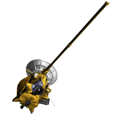
Mission Duration: The Cassini-Huygens mission launched on October 15 1997, and ended on September 15 2017.
Destination: Cassini's destination was Saturn and its moons. The destination of the Huygens Probe's was Saturn's moon Titan.
Orbit: Cassini orbited Saturn for 13 years before diving between its rings and colliding with the planet on September 15th, 2017.