
Cassini MIMI Investigation at Fundamental Technologies
Historical MIMI Memos and Notes
Cassini MIMI LEMMS Detector Logic Design:
Further
Suggestions on LEMMS Head Design
Memo to S. M. Krimigis, Don Mitchell, Erhard Kirsch, and Berend Wilken from Tom Armstrong, July 13, 1993
In response to the fax memo from Kirsch dated June 22 and the email from Mitchell dated July 2, I have reworked the provisional scheme of my June 16 memo. The full calculation results are attached for your inspection. However, let me list the major changes and highlights (I hope strengths) of this scheme.
- The assumed opening angle of the 180 degree end is 15 degrees (conical half angle).
- The 0 degree end has been calculated and is included here so that coverage of the proton spectrum up to about 10 MeV can be obtained therefrom and the 180 degree end can have a thicker foil (100 microns aluminum equivalent assumed) and use a 150 micron detector.
- In this calculation fewer detectors are used than in the June 22 Kirsch diagram. I believe that we can accomplish our objectives with a stack of D1 (150 microns), D2 (700 microns), D3 (1400 microns), B (700 microns), and A (107 microns--Galileo EPD heritage). Further, no thick, inert absorbers are assumed. The platinum and brass do not appear to be necessary to obtain the passband coverages for the protons, alphas, and oxygen. There are also ample opportunities for constructing electron channels up to a few MeV. As before, I haven't spelled out the details of the electron channels owing to the lack of this capability in PAMELA.
- In total there are 31 discrimination levels used. For the ions, most are to be set at comfortably high levels and should not require excessive gain or dynamic ranges in pulse amplitude. Coincidence/anticoincidence logic is generously used and it needs to function robustly for this design to have merit. Further, when the detectors are acquired and characterized, this design must be "tweaked" because the energy losses, thicknesses, and electronic thresholds are all coupled in an intricate way in this design. After this design is "tweaked" for the flight detector parameters, it will be necessary to set each discriminator precisely. It would be desirable to have about 1% or so precision in discriminator settings (5% might also work, but there are some close calls as you may note from the calculated tables).
- The definition of x-ray and other channels is not precluded in this design. Additional logic can be included as needed.
- Responding to the design information that Nick Paschilides needs on the performance of the electronics, I have the following intuition. This is only intuition because I haven't done number estimates of counting rates yet. I would suppose that if a pulse width of 0.1 microsecond in the preamps and amplifiers can be obtained and the strobing and logic can be done in no more than 0.2 microseconds, that this system will hold up and function acceptably throughout most of the Saturnian environment. I would expect the degradation introduced by high count rates to be graceful.
- The departures from nominal response of this design arising from omnidirectional or bidirectional effects should be minimal. It is important to keep the detector stack reasonably compact so that all detectors see the same solid angle. For bidirectionality, PAMELA must be run for the inverted stack. I haven't done that yet (this all takes a lot of time, sports fans), but I will do so in order to avoid surprises.
Table 1. Summary of passbands in July 13, 1993, provisional design
| Channel Name | Protons (MeV) | Alphas (MeV/nucleon) |
Oxygen (MeV/nucleon) |
Electrons |
| A0 | 0.030 to 0.055 | to 0.017 | ||
| A1 | 0.055 to 0.079 | 0.017 to 0.024 | ||
| A2 | 0.079 to 0.133 | 0.024 to 0.040 | to 0.016 | |
| A3 | 0.133 to 0.283 | 0.040 to 0.085 | 0.016 to 0.030 | |
| A4 | 0.283 to 0.526 | 0.085 to 0.151 | 0.030 to 0.050 | |
| A5 | 0.526 to 0.819 | 0.151 to 0.227 | 0.050 to 0.072 | |
| A6 | 0.819 to 1.630 | 0.227 to 0.427 | 0.072 to 0.128 | |
| A7 | 1.630 to 3.230 | 0.427 to 0.895 | 0.128 to 0.259 | |
| A8 | 0.895 to 3.126 | 0.259 to 6.584 | ||
| B0 | 3.275 to 4.492 | |||
| B1 | 4.534 to 10.479 | |||
| B2 | 3.125 to 4.978 | 6.581 to 6.894 | ||
| B3 | 4.979 to 9.949 | 6.894 to 23.118 | ||
| BE | ||||
| E1 | ||||
| E2 | ||||
| E3 | ||||
| P3 | 5.550 to 6.817 | |||
| P4 | 6.817 to 9.015 | |||
| P5 | 9.012 to 11.913 | |||
| P6 | 11.913 to 13.697 | |||
| P7 | 1.3697 to 29.559 | 44.081 to 146.736 | ||
| P8 | 25.753 to 59.795 | 145.901 to 496.542 | ||
| P9 | 59.795 to 276.144 | 496.549 to | ||
| H1 | 3.638 to 5.530 | |||
| H2 | 5.526 to 14.511 | 193.463 to | ||
| H3 | 11.913 to 25.676 | 193.463 to | ||
| H4 | 25.676 to 44.081 | |||
| H5 | 57.975 to 114.211 | |||
| Z1 | 7.310 to 11.913 | |||
| Z2 | 11.913 to 25.666 | |||
| Z3 | 25.666 to 193.463 |
Notes:
- Blanks in proton, alpha, and oxygen columns mean that no response is found in the interval 0.01 to 1000. MeV/nucleon.
- A missing high or low passband edge means that the passband extends beyond the range of PAMELA's computation (0.01 to 1000. MeV/nucleon).
- The electron passbands remain to be filled in.
- The channels A0 through BE are from the 0 degree end and E1 through Z3 the 180 degree end.
- Responses of the channels to particles penetrating the stack in inverse direction have not been calculated here. A separate memo will be issued later.
Table 2. Cassini MIMI LEMMS
0 Degree End, July 13, 1993;
provisional design (enhanced Galileo EPD)
| ABSORBER NAME | Contact | A | B | D3 |
| ABSORBER THICKNESSES, MICRONS | 0.1 | 107.0 | 700.0 | 1400.0 |
| ABSORBER MATERIAL | ALUM. | SILICON | SILICON | SILICON |
| THICKNESS VARIATION, MICRONS | 0.0 | 50.0 | 10.0 | 10.0 |
| CONICAL HALF ANGLE, DEGREES | 7.5 | 7.5 | 7.5 | 15.0 |
| DETECTOR NOISE, MEV | 0.0 | 0.0 | 0.0 | 0.010 |
| ELECTRONIC NOISE, MEV | 0.0 | 0.006 | 0.010 | 0.0 |
| NUMBER OF THRESHOLDS SET | 0.0 | 9.0 | 4.0 | 5.0 |
| THRESHOLD LEVEL NO. MEV 1 | 0.0 | 0.012 | 0.100 | 0.050 |
| THRESHOLD LEVEL NO. MEV 2 | 0.0 | 0.030 | 1.000 | 0.400 |
| THRESHOLD LEVEL NO. MEV 3 | 0.0 | 0.050 | 2.800 | 3.000 |
| THRESHOLD LEVEL NO. MEV 4 | 0.0 | 0.100 | 13.000 | 6.000 |
| THRESHOLD LEVEL NO. MEV 5 | 0.0 | 0.250 | 0.0 | 16.000 |
| THRESHOLD LEVEL NO. MEV 6 | 0.0 | 0.500 | 0.0 | 0.0 |
| THRESHOLD LEVEL NO. MEV 7 | 0.0 | 0.800 | 0.0 | 0.0 |
| THRESHOLD LEVEL NO. MEV 8 | 0.0 | 1.600 | 0.0 | 0.0 |
| THRESHOLD LEVEL NO. MEV 9 | 0.0 | 3.500 | 0.0 | 0.0 |
| AVERAGE PROJECTED DEPTH, MIC | 0.2 | 107.5 | 703.0 | 1424.3 |
| EST.RMS VARN.PROJ.DEPTH, MIC | 0.0 | 0.65 | 3.0 | 24.7 |
| NET RMS THICKNESS VARN. (MIC) | 0.0 | 50.0 | 10.4 | 26.6 |
| LOWER LIMIT THICKNESS (MIC) | 0.1 | 57.5 | 692.6 | 1397.6 |
| UPPER LIMIT THICKNESS (MIC) | 0.2 | 157.5 | 713.5 | 1450.9 |
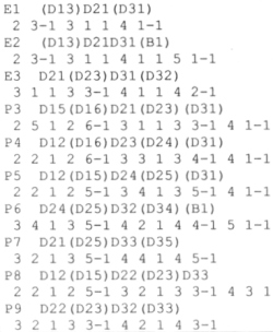
| Logic Table for
Electron and Proton Channels |
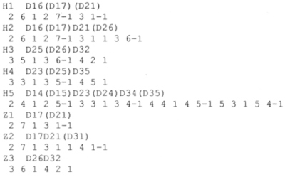
Logic Table for Helium and Medium Channels |
.jpg) |
.jpg) |
Table 3. Cassini MIMI LEMMS
Detector Logic Design,
LEMMS_J, July 12, 1993 version, 180 degree end
| ABSORBER NAME | Foil | D1 | D2 | D3 | B |
| ABSORBER THICKNESSES, MICRONS | 100.0 | 150.0 | 700.0 | 1400.0 | 700.0 |
| ABSORBER MATERIAL | ALUM. | SILICON | SILICON | SILICON | SILICON |
| THICKNESS VARIATION, MICRONS | 0.0 | 10.0 | 10.0 | 10.0 | 10.000 |
| CONICAL HALF ANGLE, DEGREES | 15.0 | 15.0 | 15.0 | 15.0 | 15.000 |
| DETECTOR NOISE, MEV | 0.0 | 0.012 | 0.007 | 0.010 | 0.010 |
| ELECTRONIC NOISE, MEV | 0.0 | 0.0 | 0.0 | 0.0 | 0.0 |
| NUMBER OF THRESHOLDS SET | 0.0 | 7.0 | 6.0 | 5.0 | 4.000 |
| THRESHOLD LEVEL NO. MEV 1 | 0.0 | 0.050 | 0.050 | 0.050 | 0.100 |
| THRESHOLD LEVEL NO. MEV 2 | 0.0 | 0.100 | 1.500 | 0.400 | 1.000 |
| THRESHOLD LEVEL NO. MEV 3 | 0.0 | 0.300 | 3.000 | 3.000 | 2.800 |
| THRESHOLD LEVEL NO. MEV 4 | 0.0 | 0.760 | 6.000 | 6.000 | 13.000 |
| THRESHOLD LEVEL NO. MEV 5 | 0.0 | 1.600 | 12.000 | 16.000 | 0.0 |
| THRESHOLD LEVEL NO. MEV 6 | 0.0 | 4.000 | 40.000 | 0.0 | 0.0 |
| THRESHOLD LEVEL NO. MEV 7 | 0.0 | 16.000 | 0.0 | 0.0 | 0.0 |
| AVERAGE PROJECTED DEPTH, MIC | 101.7 | 152.6 | 712.1 | 1424.3 | 712.1 |
| EST.RMS VARN.PROJ.DEPTH, MIC | 1.8 | 2.6 | 12.3 | 24.7 | 12.3 |
| NET RMS THICKNESS VARN. (MIC) | 1.8 | 10.3 | 15.9 | 26.6 | 15.9 |
| LOWER LIMIT THICKNESS (MIC) | 100.0 | 142.3 | 696.2 | 1397.6 | 696.2 |
| UPPER LIMIT THICKNESS (MIC) | 103.5 | 162.9 | 728.0 | 1450.9 | 728.0 |
| Logic Table for
Electron and Proton Channels |
Logic Table for Helium and Medium Channels |
 |
 |
For brevity, the figures are not included here. Please refer to the final figures.
Return to Historical MIMI Notes and Memos main page.
Return to Cassini
MIMI table of contents page.
Return to Fundamental
Technologies Home Page.
Updated 8/8/19, Cameron Crane
QUICK FACTS
Mission Duration: The Cassini-Huygens mission launched on October 15 1997, and ended on September 15 2017.
Destination: Cassini's destination was Saturn and its moons. The destination of the Huygens Probe's was Saturn's moon Titan.
Orbit: Cassini orbited Saturn for 13 years before diving between its rings and colliding with the planet on September 15th, 2017.