


Cassini MIMI Investigation at Fundamental Technologies
Historical MIMI Memos and Notes
Presentation by K. Heerlein at MIMI team meeting, October 1994
(K. Heerlein, Max-Planck-Institut Lindau)
2. Input Pulses for the Nine Energy Channels
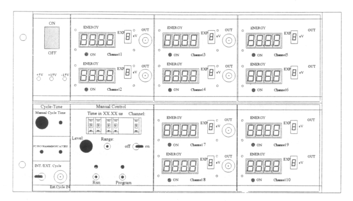
The tail pulse generator is able to generate ten separate adjustable tail pulses. The adjustment can be made directly at the device or with a PC.
For each channel, the following can be adjusted:
- the energy level(in four ranges):
Range Max Energy Min Energy Step Width 1 99.9 MeV 10 MeV 100 keV 2 9.99 MeV 1 MeV 10 keV 3 999 keV 100 keV 1 keV 4 99.9 keV ~0 keV 0.1 keV - the delay time of the pulse:
- manual in the range 0 to 99.99 ms
- per PC in the range 0 to 160 ms
In addition, it is possible to change the pulse cycle time for all channels in the range of about 100 Hz to 1 MHz.
It is also possible to trigger pulses by an external signal.
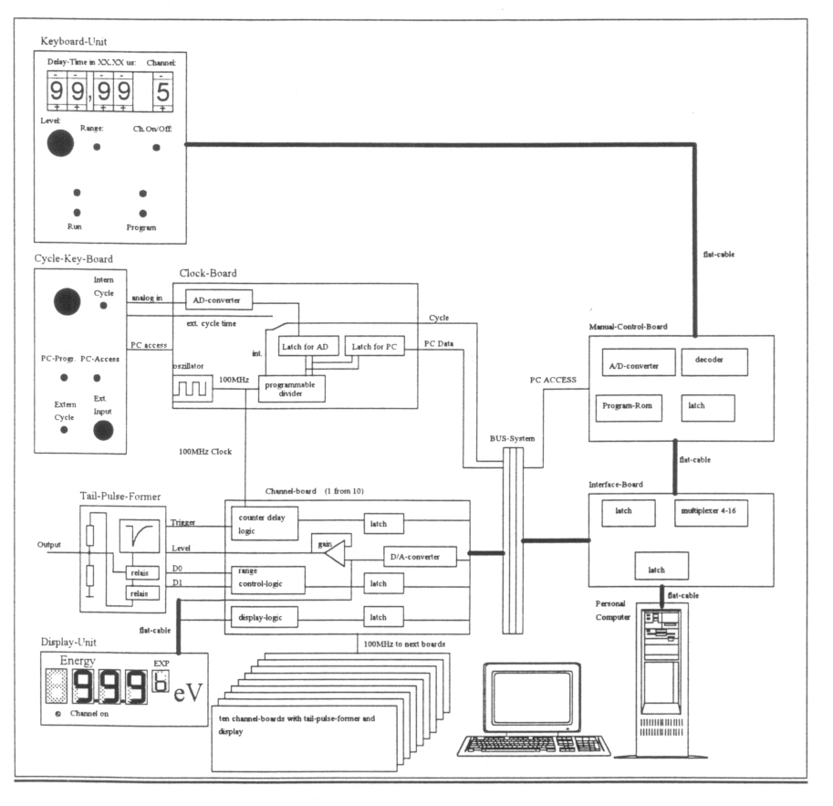
The tail pulse generator consists of four different mainboards and three daughterboards. The connection between the boards is made by a bus system:
| Motherboard | Daughterboard |
| Clock/Cycle Board | Cycle keyboard (mounted on front panel) |
| Manual Control Board | Key Unit Board (mounted on front panel) |
| Interface Board | |
| Channel Board | Tail Pulse Former Board (mounted on channel board) |
On this board the clock frequency (100 MHz) for the delay time adjustment of the tail pulses is generated. Furthermore, it contains the logic to adjust the cycle time of the pulses. This time is divided from the clock. The dividing ratio is given by the PC or it can be manually adjusted on the front panel. In addition, the cycle time can be given by an external source.
To select between manual/PC or external adjustment there is the 'Cycle Keyboard' which is mounted on the front panel. On this board one can switch between the two inputs (intern/extern); the cycle time can be adjusted by a poti, and two LEDs show if the PC is programming.
The adjustment range is (intern):
--for manual mode: about 380 Hz to 1 MHz
--for PC: 85 Hz to 1 MHz
The above values depend on the pre-divider for the 100 MHz and can be preselected by a dipswitch on the board. The maximum frequency is dependent on the time constant of the pulse.
The adjustment by PC has priority and ignores the manual selected values.
2.3.2 Manual Control Board and Key Unit
The manual control board contains the complete logic to control the generator. The channel settings can be made by the key unit board which is mounted on the front panel and connected to the manual control board by a flat cable. The adjusted values for a chosen channel are transmitted by the bus system. The data acknowledge signals are created by an EPROM.
How to program in manual mode (keys on front panel):
- In 'run mode' select the channel you want to program.
- Press 'program' (now all values for the channel settings are directly transmitted to the selected channel.
- Select the channel settings:
-delay time between 0 and 99.99 ms
-energy level range (99.9MeV/9.99MeV/999keV/99keV)
-energy level 0-99.9 (9.99/999)
In the power up situation all channels are programmed to 'default values.'
This board functions as a buffer for the incoming data signals from either PC or manual control. If there is programming by PC, shown by a 'PC PROGRAMMING' signal, only the PC signals will lead to the bus and therefore to the channels. Otherwise data from manual control will be transferred to the bus (PC has priority).
2.3.4 Channel Board and Tail Pulse Former
The generation of the pulses is made on this board. The received data is latched processed and then transferred to the onboard Tail Pulse Former. This Tail Pulse Former is in a metal case for electromagnetic shielding.
(Click on figure for larger version.)
To control the motor, it is foreseen to use VTT equipment. If it is possible, the used control program should be implemented to the test program, so that only one PC is used to control the motor and LEMMS electronics.
4. Data Acquisition of Housekeeping Data
For data acquisition of the housekeeping data during testing, there will be used an i/o card with differential analog inputs.
Return to Historical MIMI Notes and Memos main page.
Return to Cassini
MIMI table of contents page.
Return to Fundamental
Technologies Home Page.
Updated 8/8/19, Cameron Crane
QUICK FACTS
Mission Duration: The Cassini-Huygens mission launched on October 15 1997, and ended on September 15 2017.
Destination: Cassini's destination was Saturn and its moons. The destination of the Huygens Probe's was Saturn's moon Titan.
Orbit: Cassini orbited Saturn for 13 years before diving between its rings and colliding with the planet on September 15th, 2017.