


Cassini MIMI Investigation at Fundamental Technologies
Historical MIMI Memos and Notes
Presentation by K. Heerlein at MIMI team meeting, October 1994
(K. Heerlein, Max-Planck-Institut Lindau)
1. Control by Serial Communication
To control LEMMS via the serial communication, there has been developed an i/o card with a test program that runs with a PC. The program provides sending each possible command and stores the received data bytes in a file on disk. To enable a direct view of what happens, the received data also is displayed on the screen. The display shows:
- The sent command
- Status of the experiment (Result bit; did LEMMS receive the command?)
- Housekeeping values with graphic view of the last 100 values
- The 60 counter values
- The Overflow byte (counter overflow)
- Threshold levels
- The received PHA bytes
The i/o card that is used for this job has got two 8255 chips on board. One is used for the serial communications with LEMMS, the other to control the pulse generator (see below).
1.1 Structure of LEMMS Data
To understand how the serial communication works, here is a description about the incoming data from LEMMS.
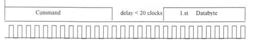
LEMMS data structure consists of 124 eight-bit blocks that are received with a 50 kHz clock rate. Between each block is a minimum time delay of two clock periods. Each block has a start bit, 8 data bits and a parity bit at the end. If the number of the 8 data bits is even, the parity bit is a one; in case of an odd amount of data bits it is zero.
The first block is received several clock periods after the last command bit was sent. The exact time delay isn't fixed at this point. In the test program, the maximum delay is 20 clock periods; that means if the last command bit was sent and the program doesn't receive any byte during 20 clock periods, a 'timeout error' is detected.
The 124 Data Bytes:
1st byte
This first byte contains the status information about the incoming data:
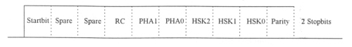
The last three bits of this byte describe the Housekeeping Data addresses:
| HSK2 | HSK1 | HSK0 | Address | Type | Value | Comment |
| 0 | 0 | 0 | 0d | voltage | -6V | |
| 0 | 0 | 1 | 1d | voltage | +6V | |
| 0 | 1 | 0 | 2d | voltage | -12V | |
| 0 | 1 | 1 | 3d | voltage | +12V | |
| 1 | 0 | 0 | 4d | voltage | +5V | |
| 1 | 0 | 1 | 5d | voltage | HV | |
| 1 | 1 | 0 | 6d | temperature | Temp 1 | 4.3mV/ºC 0ºC=1,157V |
| 1 | 1 | 1 | 7d | temperature | Temp 2 |
Bit 4 and Bit 5 describe the Pulse Height Analysis addresses:
| PHA1 | PHA0 | Address | Status | Comment |
| 0 | 0 | 0d | PHA off | |
| 0 | 1 | 1d | PHA-->A-1 | |
| 1 | 0 | 2d | PHA-->E1-1 | |
| 1 | 1 | 3d | PHA-->F1-1 |
The third bit is the 'Result of Comparison' bit (RC). This bit is high if the command that was sent before was recognized without an error. In case of an error, this bit is low.
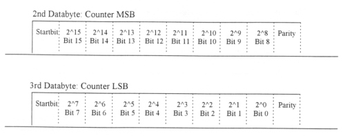
2nd - 121st byte
The following 120 data bytes contain the counting rates of the 60 counters at LEMMS. Each counter state is sent by two 8-bit bytes. The first byte is the MSB, and the second is the LSB.
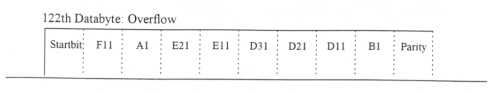
122nd byte
The 122nd byte is called the 'overflow byte.' Because of the possibility of getting very high counting rates that are higher than 16 bits, this byte shows if there has occurred an overflow on a specific counter. This allows it to make a distinction between low counting rates and overflows. An overflow will be signified by a logical high. The following integral results will occur (the sequence is not yet fixed):
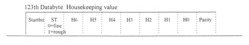
123rd byte
This byte is the 7-bit housekeeping value, signified by the Housekeeping Address in the first byte as it was described before. The 8th bit signs the resolution: it is low at fine ADC resolution, high at rough ADC resolution.
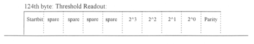
124th data byte: threshold readout
This byte contains one threshold level in 4 bits. The higher 4 bits are not used.
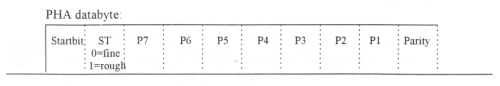
PHA Data
After sending the 124 data bytes, LEMMS is sending the PHA data each time an event occurs. Each PHA data byte contains 7 bit data and one bit resolution, equal to the Housekeeping data byte.
As soon as the DPU sends a new command, the last PHA data byte is sent completely. After that LEMMS control reacts on the new command.
Next: 1.2 Structure of LEMMS Test Program
Return to Historical MIMI Notes and Memos main page.
Return to Cassini
MIMI table of contents page.
Return to Fundamental
Technologies Home Page.
Updated 8/8/19, Cameron Crane
QUICK FACTS
Mission Duration: The Cassini-Huygens mission launched on October 15 1997, and ended on September 15 2017.
Destination: Cassini's destination was Saturn and its moons. The destination of the Huygens Probe's was Saturn's moon Titan.
Orbit: Cassini orbited Saturn for 13 years before diving between its rings and colliding with the planet on September 15th, 2017.